Saturday, March 31, 2007

Plotting 3D functions with Groovy and Java3D

In this post I'm going to show a little demo that plots 3D functions by using Groovy and Java3D.

For this demo I'm going to use the Java3D builder created for previous posts.

The TriangleArray class will be used to create the grid to plot the function . Two triangles will be create for each set of 4 points. For future posts I'm going to try to change this to support TriangleStripArray or QuadArray.

In order to create each coordinate of the plane, a function that maps between the iteration number and the real coordinate to be plotted is required. In order to do this the createMapFunc was created, this function returns a function that maps between two coordinates.


Closure createMapFunc(int x1,int x2,double y1,double y2) {
double m = (y2 - y1)/(x2 - x1);
double b = y1 - m*x1;
return { x -> m*x + b}
}

Closure createFloatMapFunc(int x1,int x2,double y1,double y2) {
Closure f = createMapFunc(x1,x2,y1,y2);
return { (float)f(it)};
}


Given this we can now create the TriangleArray data required to plot the function:


Geometry createGeometry(Closure f,double min,double max,int gridSize) {
Closure fInter = createFloatMapFunc(0,gridSize-1,min,max);
TriangleArray ta = new TriangleArray(((gridSize-1)**2)*6,
TriangleArray.COORDINATES
|TriangleArray.NORMALS
);
int idx = 0;
float x,y,z;

for ( iY in (0..(gridSize-2))) {
for( iX in (0..(gridSize-2))) {
// First triangle
x = fInter(iX);
y = fInter(iY);
z = (float) f(x,y);
ta.setCoordinate(idx,new Point3f(x,y,z));

x = fInter(iX+1);
y = fInter(iY);
z = (float) f(x,y);
ta.setCoordinate(idx+1,new Point3f(x,y,z));

x = fInter(iX);
y = fInter(iY+1);
z = (float) f(x,y);
ta.setCoordinate(idx+2,new Point3f(x,y,z));

idx += 3;

// Second triangle
x = fInter(iX+1);
y = fInter(iY);
z = (float) f(x,y);
ta.setCoordinate(idx,new Point3f(x,y,z));

x = fInter(iX+1);
y = fInter(iY+1);
z = (float) f(x,y);
ta.setCoordinate(idx+1,new Point3f(x,y,z));

x = fInter(iX);
y = fInter(iY+1);
z = (float) f(x,y);
ta.setCoordinate(idx+2,new Point3f(x,y,z));

idx += 3;
}
}
return ta;
}


The function to be plotted is a parameter to the createGeometry function.

For this example the following function will be used:


def f = { x,y -> Math.cos(x+y)*Math.sin(x-y)}


Now that we have the code to generate the 3D function geometry we can create the Java3D/Swing required elements by using the Swing, Java3D and SimpleUniverse builders.


SwingBuilder sb = new SwingBuilder();
SimpleUniverseBuilder sub = new SimpleUniverseBuilder();
Java3dBuilder jb = new Java3dBuilder();


JFrame aFrame = sb.frame(title:"Function",size:[500,500]){
panel(layout: new FlowLayout()) {
thePanel = panel(preferredSize:[500,500],
layout:new BorderLayout())
}
}

SimpleUniverse univ =
sub.simpleUniverse() {
viewingPlatform(nominalViewingTransform:true) {
orbitBehavior(
flags:OrbitBehavior.REVERSE_ALL,
bounds:new BoundingSphere(
new Point3d(0.0,0.0,0.0),
100.0))
}
viewer() {
view(minFrameCycleTime:5)
}
}

thePanel.add(univ.getCanvas(),BorderLayout.CENTER);

BranchGroup bg =
jb.branchGroup() {
transformGroup(
capability:
TransformGroup.ALLOW_TRANSFORM_WRITE) {
shape3d(geometry:createGeometry(f,-2.5,2.5,20),
appearance:polyAppearance())
}
}
bg.compile();

univ.addBranchGraph(bg);
aFrame.show()


The result of running the program looks like this:


As a last detail, the appearance of the surface is created with the createPolyAppearance function:


Appearance polyAppearance() {
Appearance app = new Appearance();
PolygonAttributes pa = new PolygonAttributes();
pa.setPolygonMode(PolygonAttributes.POLYGON_LINE);
app.setPolygonAttributes(pa);
return app;
}


Code for this experiment can be found here.

In future posts I'm going to try to add more features, like materials applied to the surface geometry, axis lines, etc.
Tuesday, March 27, 2007

Formating Fortress code with Fortify

A couple of days ago I noticed that a new tool to generate LaTeX code from Fortress source code was available. The tool is called Fortify can be found in the same page where the reference implementation is located.

In this post I'm going to try to create a little example and run Fortify to see the output of the generated LaTeX document.

One of the interesting things about Fortress is that, the language will have an alternative syntax that uses a lot of graphical symbols that will make a Fortress program look like a mathematical document.

For this test I took my old Numerical Analysis book and copied the Newton Raphson algorithm.

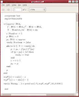
The program looks like this:


component Test

export Executable

nr(approx:RR64,f : RR64 -> RR64, f' : RR64 -> RR64,
N : Number,tol : RR64) = do

i:Number := 1
p:RR64 := 0
p0:RR64 := approx
ready:Boolean := false

while(i <= N AND NOT ready) do
p := p0 - f(p0)/f'(p0)
if |p - p0| < tol then
ready := true
end
i := i + 1
p0 := p
end

p
end

myF(x) = cos(x) - x
myF'(x) = - sin(x) - 1

run(a:String...) = print nr(1.5,myF,myF',10,0.0001)

end


Fortify is a tool that works inside Emacs. So I loaded fortify inside Emacs:


(load "..../fortify.el")


Then loaded Fortify by calling M-x fortify.

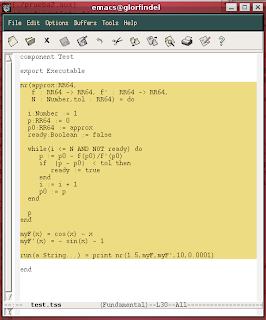
Selected the code:


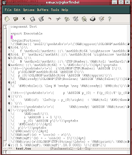
And pressed M-&, then LaTeX code is generated.


To the generated code I added the LaTeX document declaration elements and imported a macros file included with Fortify.


\documentclass{article}
\usepackage{url, amssymb, amsmath, amsthm, stmaryrd, xspace}
\usepackage{amsfonts, graphicx, fullpage, times, hyperref}
\input ../fortify/fortify-macros

\begin{document}

....

\end{document}


After running LaTeX the code looks like this:

Thursday, March 15, 2007

An implementation of 'du -s *' in Powershell

While reading about Powershell I noticed that there's no out-of-the-box way(that I know of) to do something similar to 'du -s *' in Unix/Linux. In this post I'm going to show how to implement a similar functionality.

The -s option of the du is used to show only a the total size each argument. This is very useful when trying to determine which directories or files are taking too much space. For example:


$ cd /cygdrive/c/Python25/
$ du -bs *
4794012 DLLs
4160038 Doc
13817 LICENSE.txt
13752327 Lib
88573 NEWS.txt
56691 README.txt
547784 Tools
382592 include
948600 libs
24064 python.exe
24576 pythonw.exe
3248808 tcl
4608 w9xpopen.exe


For better results the output could be combined with sort.


$ du -bs * | sort -n
4608 w9xpopen.exe
13817 LICENSE.txt
24064 python.exe
24576 pythonw.exe
56691 README.txt
88573 NEWS.txt
382592 include
547784 Tools
948600 libs
3248808 tcl
4160038 Doc
4794012 DLLs
13752327 Lib


In order to implement this in Powershell (with the little knowledge I have from it) I wanted to implement the following strategy


  1. get all the child elements from the base directory

  2. for each element get the total size

  3. generate a tuple with the element name and the total size


In order to implement #1 a common get-childitem command was used. To implement #2, a combination of foreach-object + get-childitem -r + measure-object was used. And finally for #3 the select-object command was used.

One implementation for this functionality is the following:


function directory-summary($dir=".") {
get-childitem $dir |
% { $f = $_ ;
get-childitem -r $_.FullName |
measure-object -property length -sum |
select @{Name="Name";Expression={$f}},Sum} }


Running this command in the same directory shows:


PS C:\Python25> directory-summary

Name Sum
---- ---
DLLs 4794012
Doc 4160038
include 382592
Lib 13752327
libs 948600
tcl 3248808
Tools 547784
LICENSE.txt 13817
NEWS.txt 88573
python.exe 24064
pythonw.exe 24576
README.txt 56691
w9xpopen.exe 4608


We can also sort the results:


PS C:\Python25> directory-summary | sort sum

Name Sum
---- ---
w9xpopen.exe 4608
LICENSE.txt 13817
python.exe 24064
pythonw.exe 24576
README.txt 56691
NEWS.txt 88573
include 382592
Tools 547784
libs 948600
tcl 3248808
Doc 4160038
DLLs 4794012
Lib 13752327


Maybe there's a shorter/better way to implement this, however it was very interesting and fun to learn a little bit more about Powershell while trying to solve this.

Thursday, March 8, 2007

More Java3D and Groovy Builders

In the previous post, a basic Builder for Java3D was shown. For this post I've decided to take one another example from the Java3D distribution and try to implement the scene creation code by using the builder. Also I've received nice suggestions that and I'm going to implement.


The example that I'm going to use is SphereMotion.java which is a nice demonstration of spheres, animation and lights.

The scene creation code of this example can be found in the createSceneGraph method of the SphereMotion class in SphereMotion.java. I'm not going to show the code in this post.

This example contains the following elements:


  1. Uses the Background class to set the background color.

  2. Creates a big Sphere which is the central element of the scene

  3. Conditionally creates a PointLight, DirectionalLight or SpotLight for the Sphere illumination.

  4. Uses a PositionInterpolator and RotationInterpolator to perform an animations

  5. Uses AmbientLight for general scene illumination.


Helpers for Background, Sphere, PointLight, DirectionalLight, SpotLight, PositionInterpolator and AmbientLight were created.

According to the suggestions, we can use Groovy array literals to specify attribute values that require classes. For example instead of using "alpha: new Alpha(-1,4000)" use "alpha: [-1,4000]". This makes the code more readable.

The flexibility of having the control over attribute and element creation let's you support many ways of doing the same thing. For example, I wanted to allow the "position" attribute of the PointLight class to be specified as an instance of the Point3f class(for example "position:new Point(0.0f,0.0f,0.0f)) or as an array of three elements (for example "position:[0.0f, 0.0f, 0.0f]"). To implement this in the builder, the PointLightHelper code for the position attribute looks like this:


public class PointLightHelper extends LightHelper {

protected void applyAttributes(Node aNode,
Map attributes) {
super.applyAttributes(aNode, attributes);
PointLight pl = (PointLight)aNode;

// Check the position attribute
if (attributes.get("position") != null) {
Object value = attributes.get("position");
if (AttributeHelper.isArrayList3fTuple(value)) {
pl.setPosition(
AttributeHelper.arrayListToPoint3f(
(ArrayList)value));
} else
if (value instanceof Point3f) {
pl.setPosition((Point3f)value);
}
}
...


where


public static Point3f arrayListToPoint3f(ArrayList a) {
Vector3f result;
return
new Point3f(
((Number)a.get(0)).floatValue(),
((Number)a.get(1)).floatValue(),
((Number)a.get(2)).floatValue());
}

public static boolean isArrayList3fTuple(Object value) {
boolean result = false;
if (value instanceof ArrayList &&
((ArrayList)value).size() == 3 ) {
ArrayList a = ((ArrayList)value);
result =
a.get(0) instanceof Number &&
a.get(1) instanceof Number &&
a.get(2) instanceof Number;
}
return result;
}


The TransformGroupHelper class was also modified so more specific transformations can be specified. For example a I wanted to create a transform group to rotate on Y axis only. To solve this an attribute rotY(and rotX and rotZ) was created to support this directly on the TransformGroupHelper. This attribute was implemented as:


if (key.matches("rot(X|Y|Z)") &&
((value instanceof Number) )) {

double dValue = ((Number)value).doubleValue();

Transform3D theRotationTransform =
new Transform3D();
tg.getTransform(theRotationTransform);

switch(Character.toUpperCase(
key.charAt(key.length() - 1))) {
case 'X':
theRotationTransform.rotX(dValue);
break;
case 'Y':
theRotationTransform.rotY(dValue);
break;
case 'Z':
theRotationTransform.rotZ(dValue);
break;
}
tg.setTransform(theRotationTransform);
}


Once having the helpers for the new elements implemented, the only thing missing to resolve was to translate the scene creation code to the builder. One of the major issues was the creation of the Light object. In the original code, the Light was created like this:


switch (lightType) {
case DIRECTIONAL_LIGHT:
lgt1 = new DirectionalLight(lColor1, lDirect1);
lgt2 = new DirectionalLight(lColor2, lDirect2);
break;
case POINT_LIGHT:
lgt1 = new PointLight(lColor1, lPoint, atten);
lgt2 = new PointLight(lColor2, lPoint, atten);
break;
case SPOT_LIGHT:
lgt1 = new SpotLight(lColor1, lPoint, atten, lDirect1,
25.0f * (float)Math.PI / 180.0f, 10.0f);
lgt2 = new SpotLight(lColor2, lPoint, atten, lDirect2,
25.0f * (float)Math.PI / 180.0f, 10.0f);
break;
}

...

l1Trans.addChild(lgt1);
l2Trans.addChild(lgt2);


This means that the creation of the instance of the desired light is a parameter of the program. Also another issue was that two lights were created and different parents are assigned to each one. In order to support this we split the creation of both lights into two different switch statements.

The final code for the creation of this scene looks like this:


public BranchGroup createSceneGraph() {
Color3f eColor = new Color3f(0.0f, 0.0f, 0.0f);
Color3f sColor = new Color3f(1.0f, 1.0f, 1.0f);
Color3f objColor = new Color3f(0.6f, 0.6f, 0.6f);
Color3f lColor1= new Color3f(1.0f, 0.0f, 0.0f);
Color3f lColor2= new Color3f(0.0f, 1.0f, 0.0f);
Color3f alColor= new Color3f(0.2f, 0.2f, 0.2f);
Color3f bgColor= new Color3f(0.05f, 0.05f, 0.2f);

TransformGroup t1;
TransformGroup t2;

Java3dBuilder j3b = new Java3dBuilder()

BoundingSphere bounds =
new BoundingSphere(new Point3d(0.0,0.0,0.0), 100.0);

// Create the root of the branch graph
BranchGroup objRoot =
j3b.branchGroup() {
transformGroup(scale:0.4) {
background(color:new Color3f(0.05f, 0.05f, 0.2f),bounds:bounds)
sphere(radius:1.0f,
flags:Sphere.GENERATE_NORMALS,
divisions:80,
material:new Material(objColor,
eColor,
objColor,
sColor,
100.0f),
lighting:true
)
t1 = transformGroup(
capability:TransformGroup.ALLOW_TRANSFORM_WRITE){
transformGroup(
translate:[0.0, 0.0, 2.0])
{
sphere(radius:0.05f,coloringAttributes:lColor1)
switch(lightType) {
case DIRECTIONAL_LIGHT:
directionalLight(color:lColor1,
direction:[0.0, 0.0, -2.0],
influencingBounds:bounds)
break;
case POINT_LIGHT:
pointLight(color:lColor1,
position:[0, 0, 0],
attenuation:[1,0,0],
influencingBounds:bounds)
break;
case SPOT_LIGHT:
spotLight(color:lColor1,
position:[0, 0, 0],
attenuation:[1,0,0],
direction:[0.0, 0.0, -2.0],
spreadAngle:25.0f * (float)Math.PI / 180.0f,
concentration:10.0,
influencingBounds:bounds)
break;
}
}
}
t2 = transformGroup(
capability:TransformGroup.ALLOW_TRANSFORM_WRITE){
transformGroup(
translate:[0.5, 0.8, 2.0])
{
sphere(radius:0.05f,coloringAttributes:lColor2)
switch(lightType) {
case DIRECTIONAL_LIGHT:
directionalLight(color:lColor2,
direction:[-0.5, -0.8, -2.0],
influencingBounds:bounds)
break;
case POINT_LIGHT:
pointLight(color:lColor2,
position:[0, 0, 0],
attenuation:[1,0,0],
influencingBounds:bounds)
break;
case SPOT_LIGHT:
spotLight(color:lColor2,
position:[0, 0, 0],
attenuation:[1,0,0],
direction:[-0.5, -0.8, -2.0],
spreadAngle:25.0f * (float)Math.PI / 180.0f,
concentration:10,
influencingBounds:bounds)
break;
}
}
}
ambientLight(color:alColor,
influencingBounds:bounds)
rotationInterpolator(alpha:new Alpha(-1, Alpha.INCREASING_ENABLE,
0, 0,
4000, 0, 0,
0, 0, 0),
target:t1,
axisOfTransform:new Transform3D(),
schedulingBounds:bounds,
minAngle:0.0f,
maxAngle:Math.PI*2.0f);
rotationInterpolator(alpha:new Alpha(-1, Alpha.INCREASING_ENABLE,
0, 0,
1000, 0, 0,
0, 0, 0),
target:t2,
axisOfTransform:new Transform3D(),
schedulingBounds:bounds,
minAngle:0.0f,
maxAngle:0.0f);
positionInterpolator(
alpha:new Alpha(-1,
Alpha.INCREASING_ENABLE |
Alpha.DECREASING_ENABLE,
0, 0,
5000, 0, 0,
5000, 0, 0),
target:univ.getViewingPlatform().getViewPlatformTransform(),
yAxisOfTransform:(-1*Math.PI/2.0),
schedulingBounds:bounds,
start:2.0f,
end:3.5f);


}
}
objRoot.compile();

return objRoot;
}


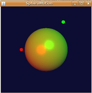
The result is the same as the Java example:


If someone wants to look at the code of this experiment, it can be found here.

In future posts I'm going to try to implement more Java3D functionality into the builder.